


USE THE BACK ARROW AFTER CLICKING ON THESE LINKS
| All content on this website was generated by Allan L. Flowers and is subject to usage restrictions. It is provided here for educational and informational use only. Limited use of some materials, with proper attribution, etc, may be possible. Contact: allanflowers@yahoo.com |
SIEMENS- SCHUCKERT D.III BIPLANE
| One of my favorite WW-I subjects was the SS_D.III, a late war biplane with a very quirky look and phenomenal performance for its time. I had been working on an Alias version of this aircraft when approached by Chris Davies of CD Scaledesigns, a German model kit maker of WW-I planes. I had been making my Sopwith PUP from Chris's kit and he asked me if I would consider doing a Beta build on another model under development. I declined but offered to work with him on the D.III. He accepted and we were off. In the end, his company went out of the business (he, like most people in this industry, has a DAY job) but not before he had produced all the prototype parts for a D.III kit. In fact, I still have the parts to a SECOND model sitting on the shelf in my garage :) Anytime I feel the need for a new project and have a spare 18 months in my schedule, I might take it up. In the meantime, this model is on display at the San Diego Air and Space Museum, where I donated it. http://sandiegoairandspace.org/ |


I always loved the graphic paint scheme on this strange aircraft.
We will see more about Vice Lieutenant Reimann later on the page.
These are RC models and MUST fly or there is no point. After
hundreds of hours building, it would be easy to hang them up
on the ceiling but that would be like adopting a child and
locking him in a room.
hundreds of hours building, it would be easy to hang them up
on the ceiling but that would be like adopting a child and
locking him in a room.
These are from the
maiden flight, which
was a terrifying
experience.
maiden flight, which
was a terrifying
experience.
| Shown in slightly muted colors to better express the historical nature of this aircraft. |
The model survived and here I am :)
A photo composite on Photoshop.
(Kawaii moMo)
(Kawaii moMo)
Sometimes the maiden flight is fine but the
second one goes very very bad.
second one goes very very bad.


These files are for a vacformed dummy engine, which never actually
came to be. Nonetheless, they guided my dummy engine build.
came to be. Nonetheless, they guided my dummy engine build.


The longerons had to be skewed in order
to place the structure behind the eventual
panel lines.
to place the structure behind the eventual
panel lines.
A look at all the front fuselage details.
The attachment of the wing spanners to the
lower wing was an important scale issue.
lower wing was an important scale issue.
An overview of the model, with all the
flying surface structures.
flying surface structures.
The linkages to the rear are all via
cables via plastic tubing.
cables via plastic tubing.
Alias rendering of the original engine concept.
This is a wooden fixture for
soldering the cabane elements.
soldering the cabane elements.
CAD files for the many dual
layer fuselage FORMERS.
layer fuselage FORMERS.
Alias surface study for the wing fillet.
Another Alias workout of surfacing
for wing fillets.
for wing fillets.
I am using the curvature "comb" tool
on the fuselage construction curves.
on the fuselage construction curves.
I had considered making the control stick being
linked into the actual servo movements so it was
important to understand the plane's engineering.
linked into the actual servo movements so it was
important to understand the plane's engineering.
This would have been a vacform
tool for the lower wing fillets.
tool for the lower wing fillets.
A good overview from the side.
Constructing the fuselage on the two "rails".
The scale propeller was a several
week project, to insure accuracy.
week project, to insure accuracy.
Landing gear wires were provided to my design by CD Scaledesigns.
These files reflect the CAD development.
These files reflect the CAD development.
Wing assembly over the drawing
insures build accuracy.
insures build accuracy.
Fuselage layout details.
In order to keep the weight forward, and avoid
adding ballast weight, I positioned all the
servos forward in the fuselage. This requires
cable activation to the rear surfaces.
adding ballast weight, I positioned all the
servos forward in the fuselage. This requires
cable activation to the rear surfaces.
Fuselage packaging.
These graphics were produced for
the little fuel gauge on the cowl.
the little fuel gauge on the cowl.
The D.III was powered by a Siemens Halski
eleven cylinder engine which was both its
strength and eventual Achilles heel. I wanted the
dummy engine to be as accurate as possible.
eleven cylinder engine which was both its
strength and eventual Achilles heel. I wanted the
dummy engine to be as accurate as possible.
CAD DESIGN in ALIAS:
ACTUAL BUILD, in metal and wood:
RC
AIRPLANES
3
AIRPLANES
3
SIEMENS
SCHUCKERT D.III
CLASSIC
TWIN TURBOPROP
SCHUCKERT D.III
CLASSIC
TWIN TURBOPROP


The box from Germany arrives!
I am monitoring the build with the
Alias files on my laptop.
Alias files on my laptop.
The formers are shown here. Each is a two layer
lite-ply/balsa composite, grain running differently.
lite-ply/balsa composite, grain running differently.
These are the parts for the basic box, where
the engine, tank, servos, etc. are all installed.
the engine, tank, servos, etc. are all installed.
My build concept was to assemble the formers on two build RAILS, pinned to the master
drawing. This worked really well and the accuracy and speed of construction was excellent.
drawing. This worked really well and the accuracy and speed of construction was excellent.
This graphic was dye-sub printed onto the master cotton sheet
(aprox. 60" wide). It included all the wing surfaces plus wheel
covers and interspan parts.
Working from historical drawings and data, the camo pattern was
created in accurate colors based on color chips from a qualified
and well known WW-I historian, Dan san Abbott.
The fabric was glued to the structure and shrunk with dope, like
the old planes.


CLASSIC & CLASSIC SPORT
I produced about sixty of these kits. They flew
well and were quite popular with their owners.
well and were quite popular with their owners.
One of my customers with his model and his build.
An early ad for the kit. Not the most
beautiful piece of graphics, I'm afraid.
beautiful piece of graphics, I'm afraid.
These last five images were from the build
manual, quite possibly the best in the RC
industry at the time.
manual, quite possibly the best in the RC
industry at the time.


More skinning details. Panels were attached with
both contact cement (for quick location) and
TiteBond. Fillet skins were particularly difficult.
both contact cement (for quick location) and
TiteBond. Fillet skins were particularly difficult.
Accurate wheels required numerous parts
including wires to reflect the proper
construction. Tires are automotive heater hose.
including wires to reflect the proper
construction. Tires are automotive heater hose.
The under carriage was a big project, based on
piano wire structure with wood overlays. Final
finish was aluminum skins with a little flange
and rivets on the rear edges.
piano wire structure with wood overlays. Final
finish was aluminum skins with a little flange
and rivets on the rear edges.


The control concept demanded many
custom metal linkages be created.
custom metal linkages be created.
Metal forming requires robust wooden forms. For the louvers, they were done one row at a time.
This part was then lined with wood. The metal part at the tail was rather easy by comparison.
This part was then lined with wood. The metal part at the tail was rather easy by comparison.


The interwing struts have an unusual
attachment on both top and bottom. I had
to make custom brass hardware.
attachment on both top and bottom. I had
to make custom brass hardware.
Covering and paint details are tedious but
cannot be rushed. Notice the camo scheme
on the wing tops are different than the lowers.
cannot be rushed. Notice the camo scheme
on the wing tops are different than the lowers.
These cockpit details were fun to make.


The fuselage is shown here after
skinning, ready for sanding.
skinning, ready for sanding.
A view of the metalwork on the
fuselage of the D.III
fuselage of the D.III
Scale wing structure includes a torsion
bar link for aileron control.
bar link for aileron control.


The cowl was spun in foam, glassed and finished.
The spinner was clay modeled, cast & laid up in
glass and resin. Both were then covered in foil.
The spinner was clay modeled, cast & laid up in
glass and resin. Both were then covered in foil.
| This prop is layered from two different wood, then carved and sanded to shape. |
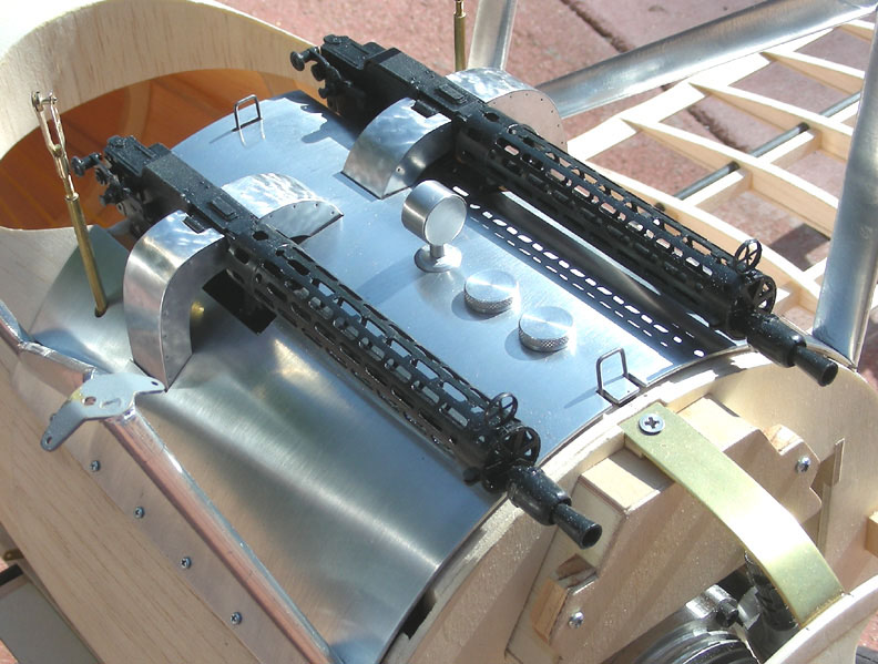
| The nearly finished gun deck with all the details including Williams Bros. guns. |
| Here all the parts have been lightly "weathered" for scale realism. |
Flight photos
by Del Perena
by Del Perena
This design was done when I was working in San Francisco at the Academy of Art University at
the Nissan Design Lab (2001-2004). One of the instructors had assigned his Product Design
class an aircraft project in response to request from a small manufacturer with a reverse
sweep wing design. It was a intriguing project so I took a shot at it, resulting in this Alias CAD
solution for a tight four-place business plane powered by two small turboprops.


Twin Turboprop Business Craft
